|
Home ||
High Power Rocketry ||
Experimental Rocketry
This page contains an overview of the different
methods and styles. For design details, see the
design pages.
Casings for experimental motors are most typically one of three materials,
metal (usually aluminum), paper (wound with an adhesive) and PVC pipe.
You can read my 1979 manual to see how to make paper casings. I have
not yet got into metal casings, though that would be the logical next step
after PVC. PVC pipe won't hold the pressure that metal will but it
will hold a respectable amount. So since my most recent experience has
been exclusively PVC, that is where I will begin.
PVC pipe comes in sizes for all but the smallest motors a person might want
to build. It comes in 1/4" and 3/8" but I haven't found any around
here. See the table below for the various sizes. Another
interesting note is that regardless of schedule or pressure rating or
material (PVC or Steel) the OD for a given nominal size is the same in all
cases and only the ID changes based on the material and pressure rating.
So a 3/4" schedule 80 steel pipe has the same OD as a 3/4" 125 psi PVC pipe.
The OD, ID and wall thickness are not exact. They will vary by several
thousanths of an inch. So when you make a grain in a pice of PVC pipe
and then insert it into a PVC Casing, you will find that you can turn the
grain and it will be tight at some points and as you turn it, it will be the
loosest at some other point. This is not a problem.
It is interesting that when calculating the burst pressure of PVC pipe, the
larger the pipe is, the lower the burst pressure is.
To make a casing, you simply cut a piece of pipe the correct length. I
use a steel cutting blade on my table saw but any blade will work, or you
can use a hack saw, hand saw, band saw, or just about any kind of saw (some
work better than others and some make cleaner cuts than others). If
you don't have a table saw or band saw, you can use a miter box and saw to
help make square cuts. I use a steel cutting blade because I cut a lot
of steel on my table saw and I found it makes a nice clean cut in PVC.
I use my table saw as opposed to a hack saw because it makes a nice square
cut with a minimum of trimming required. After cutting the pipe, you
can use a knife or a piece of sandpaper to clean off any rough edges or
hanging bits. Clean up both the inside and outside edges. A
slight bevel on the inside edge is extra helpful in some situations such as
loading tight grains or inserting retainer rings.
Ultimate tensile strength (The stress at which it will fracture) of PVC is
listed as 7450 psi. To find the total force (F) acting on a 1" length
of pipe in the radial (tangential) direction, you multiply the pressure (P)
by the inside diameter (d). F=Pd. The stress (S) is found by
dividing that force by the cross sectional area (A) of the pipe wall in one
inch. The outside diameter is D. Then, A=(D-d) and S=F/A or S =
Pd/(D-d). Since we know the ultimate stress, we can solve for the
pressure: Pt = S(D-d)/d. So for a 1/2" nominal pipe, D = .840, d =
.602, P = 7450 x (.840 - .602) / .602 = 2945 psi.
The calculation for the axial stress is similar. The force from the
pressure is the pressure times the area of the pipe ID disk or Pπ r2 or F = Pπ(d/2)2. The area of the pipe is the outside diameter disc minus
the inside diameter disk or
A = π [(D2-d2)/4].
Again S = F/A. So S = Pπ(d/2)2/π [(D2-d2)/4]
which looks kind of messy but when we reduce it down we get something
slightly more managable, S = Pd2(/(D2-d2)
and solving for P, Pa = S(D2-d2)/d2.
For that same 1/2" pipe, the failure pressure is 7450(.8402-.6022)/.6022
= 7055 psi. As it turns out the limiting factor is always the
tangential stress.
|
PVC Pipe |
125 psi |
200 psi |
Schd 40 |
Schd 80 |
|
Nominal Size |
OD
(in.) |
ID
(in.) |
Burst Pressure (PSI) |
ID
(in.) |
Burst Pressure (PSI) |
ID
(in.) |
Burst Pressure (PSI) |
ID
(in.) |
Burst Pressure (PSI) |
|
1/4 |
.540 |
|
|
|
|
.354 |
4203 |
.282 |
7319 |
|
3/8 |
.675 |
|
|
|
|
.483 |
3180 |
.4073 |
5400 |
|
1/2 |
.840 |
|
|
|
|
.608 |
3053 |
.546 |
4307 |
|
3/4 |
1.050 |
.935 |
916 |
.915 |
1099 |
.810 |
2370 |
.722 |
3634 |
|
1 |
1.315 |
|
|
1.175 |
888 |
1.033 |
2184 |
5 |
3239 |
|
1 1/4 |
1.660 |
1.525 |
660 |
|
|
1.364 |
1736 |
1.256 |
2582 |
|
1 1/2 |
1.900 |
|
|
|
|
1.592 |
1548 |
1.476 |
2298 |
|
2 |
2.375 |
|
|
|
|
2.049 |
1273 |
1.913 |
1932 |
|
3 |
3.5 |
|
|
|
|
3.042 |
1204 |
2.864 |
1777 |
Also see Motor Design Tables
(bottom of page)
|
The only difference between the nozzle and header is that the nozzle has a
hole through it and it is cast first. A form is used to make the
nozzle throat. (See below). After the nozzle is set up, then the
propellant grains can be loaded into the casing, and then the header is
cast. Actually the header will also have a smaller hole in it if an
ejection charge is included as part of the motor.
Quick Setting Concrete.
  Nozzles and Headers are made from quick setting concrete. See pictures
under "Circumferential Holes" in the "Retaining Methods" on this page below.
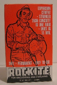
There are a number of brands and several types. I have found that Rockite is also very good. It has a high strength and expands when it
hardens helping to lock the nozzle or header into the motor tube. Many
people use and recommend Durham's Rock Hard Water Putty and it also works
well. DAP also makes a water putty that probably would Nozzles and Headers are made from quick setting concrete. See pictures
under "Circumferential Holes" in the "Retaining Methods" on this page below.
There are a number of brands and several types. I have found that Rockite is also very good. It has a high strength and expands when it
hardens helping to lock the nozzle or header into the motor tube. Many
people use and recommend Durham's Rock Hard Water Putty and it also works
well. DAP also makes a water putty that probably would
Quikrete will also work and it also expands as it cures
but it has sand in it and that makes it not nearly as nice to work with.
Rockite and the water putties are like working with plaster of Paris both in
the wet and the cured conditions. Quikrete is like working with
concrete. It is gritty and especially on smaller nozzles, it is harder
to form the convergent and divergent cones. It makes a rough surface
and in a nozzle, that is definitely not desirable. Any surface
irregularity disrupts the flow and can even prevent the flow from going
supersonic in the divergent section.
They all set up in between 10 and 30 minutes and
get stronger as they cure. I have
actually fired motors that had only set up for two or three hours but if you
expect or are designing for pressures above 200 psi, it is a good idea to
let the finished motors cure for a couple days. Rockite and
Quikrete both claim to expand as they cure while Durham's just says it will
not shrink. As pressure climbs higher than a good design, any motor
will first leak and then blow out the nozzle and/or header. A
bead of RTV at the pvc pipe--nozzle/header junction will help to contain a
higher pressure but eventually, that will also fail. The increased
pressure will stretch out the pvc and cause a gap between the concrete and
pvc pipe and the gases will escape. At a high enough pressure, either
the concrete will fail or the retaining system will fail. This is what
is desired. You never want the motor casing walls to fail as this can
be much more dangerous.
For a stable design in a reasonable pressure band, maybe 200 to
450 psi, nozzles made with quick setting cement or water putty work quite
well.
Mixing
The material is a dry powder. It is mixed with water (Rockite uses a
ratio about 3:1 or 4:1 Rockite to Water by volume) to a consistency of
between a thick but pourable mix to a near putty like mix. Somewhere
between is probably best but I have used both and don't see much difference
in the finished product. The directions aren't very specific either so
apparently it isn't very critical.
I started using paper dixie cups but found I liked using the smaller of a
set of cheap stainless steel measuring cups (1/4 cup) because the dixie cups
would get wet, paper would come off and mix in with the concrete, and it was
twice as deep as my measuring cup. After each little batch, I just
wipe out the miniature pan with a paper towel and I am ready for a new
batch. I got a package of bamboo shish kabob skewers and use them for
mixing, tamping, bubble releasers, and all sorts of uses. I use them
for mixing my concrete and then use it to help scoop it into the casing.
Strength
The longer the concrete cures, the stronger it gets. My pail of Quikrete says right on the pail that its compression strength exceeds 2000
psi in two hours and exceeds 7000 psi in 28 days. That is quite a
difference. Rockite has a compression strength of 4500 psi in two
hours. The different kinds of strengths are: tensile, compressive,
shear, and torsional. For any given material, depending on whether it
is ductile or brittle and other factors, each strength type can be
different. Shear and tensile strength for concrete is less than its
compressive strength. That is why rebar reinforcement is put into
concrete to give it more tensile and especially shear strength. What we need
in the nozzles and headers is shear strength and abrasion resistance.
Neither are all that great but inserts of graphite, steel, or other metal
alloys can be used if desired to get around
erosion due to its low abrasion resistance. We are stuck with the
existing shear strength of the concrete unless someone comes up with some
kind of additive. In the meantime, we just design around it.
Retention Methods
You can't just pour concrete into a piece of pipe. Even if it seems
like it is stuck in tight, only a small amount of pressure will push it out
because it is relying only on friction to keep it in. To hold the
nozzle and header or forward closure in place, you need to have a mechanical
method. There has to be part of the motor tube holding in part of the
concrete so that it forces the concrete to shear in order to eject the
nozzle or header.
Caps & Fittings
Caps and fittings used for the nozzle retainer and forward closure proved
the most strength and may be the easiest method. Here are the
disadvantages. The caps are a lot more expensive than the amount of
pipe used for a motor and other fittings are even more expensive.
Fittings increase the OD so they increase the diameter of the motor mount
tube that is required and if you are building a minimum diameter rocket
(used for high altitude), the minimum diameter has to be larger. In my
opinion, they also just look bad. I personally like the looks of
straight cylinders with nothing on the outside. This method is more
appropriate for larger motors in my opinion, though any of the other methods
can also be used.
All these illustrations are shown without ejection charges. If an
ejection charge is to be used, see the illustrations in that section.
 Caps and other fittings are the most common method of retaining nozzles and
headers. Actually, if you use a cap or other fitting to hold in the nozzle, you
might as well use a cap on the other end because then both ends will have
the same OD so the motor will fit better into a motor mount tube and also
you will have the same strength on both ends. No concrete is used in
the forward closure (the bottom cap in the illustrations). You
just need to coat the inside with RTV so the cap doesn't melt. The
other end is protected by the concrete and the pipe (motor casing tube) is
protected by the concrete and the grain inhibitor sleeve. Caps and other fittings are the most common method of retaining nozzles and
headers. Actually, if you use a cap or other fitting to hold in the nozzle, you
might as well use a cap on the other end because then both ends will have
the same OD so the motor will fit better into a motor mount tube and also
you will have the same strength on both ends. No concrete is used in
the forward closure (the bottom cap in the illustrations). You
just need to coat the inside with RTV so the cap doesn't melt. The
other end is protected by the concrete and the pipe (motor casing tube) is
protected by the concrete and the grain inhibitor sleeve.
The normal
way to form the nozzle is to glue the cap onto the end of the motor tube (pvc pipe) and then
pour concrete for the nozzle through the hole in the cap.
An alternate method that can sometimes be used if the nozzle is small is to
fill the cap part way full of cement and form the nozzle in it first and
then when it sets up, it is glued onto the pipe with the remaining portion
that does not have cement in it.
  Another fitting that can be used is a female adapter with an NPT thread on
one end and a slip fit (glue surface) on the other end. The concrete
is cast into Another fitting that can be used is a female adapter with an NPT thread on
one end and a slip fit (glue surface) on the other end. The concrete
is cast into
the threaded end and the threads retain the concrete. After the
concrete has set up and the nozzle has been formed in it, then the coupling
is glued onto the motor tube (pvc pipe section).
The forward closure (actually shown on the bottom in these illustrations) is
simply a pipe cap. After the nozzle fitting is glued in place, the fuel
grain(s) are inserted into the case. The pipe cap for the forward
closure is coated with RTV silicone rubber on the inside and allowed to
cure. The cap is then glued onto the forward end of the motor tube.
Other fittings are also possible, especially with larger motors like 2" and
larger. Reducer fittings alone or with male adapters can be used.
The concepts are the same, something is needed to grab the concrete and keep
it from being ejected without shearing the concrete itself.
Circumferential Holes
 I first saw
this method on Dan Pollino's
Inverse Engineering web site. See his pictures
here. I used his method but scaled it down to the smaller motors
that I was testing. This method has the least strength of the
different methods because the only area of concrete that must shear in a
failure is the concrete in the holes. However, it still makes a nice
smooth outside finish, gives you the minimum outside diameter, and has the
benefit of no additional components. I have used this method with an
internal pressure of 400 psi without a problem. One thing to make sure
of is that you have enough concrete above the holes. If the inside of
the nozzle plug is too close to the holes, the exhaust gasses can find there
way and leak out of the holes. I found the time to make these cases
was about equivalent to the next method -- ID retaining ring. To
increase the strength, a second row of holes could be added but that would
also increase the length of the nozzle and header and would add extra weight
and length to the casing. It is better to use the internal ring to
increase strength. I first saw
this method on Dan Pollino's
Inverse Engineering web site. See his pictures
here. I used his method but scaled it down to the smaller motors
that I was testing. This method has the least strength of the
different methods because the only area of concrete that must shear in a
failure is the concrete in the holes. However, it still makes a nice
smooth outside finish, gives you the minimum outside diameter, and has the
benefit of no additional components. I have used this method with an
internal pressure of 400 psi without a problem. One thing to make sure
of is that you have enough concrete above the holes. If the inside of
the nozzle plug is too close to the holes, the exhaust gasses can find there
way and leak out of the holes. I found the time to make these cases
was about equivalent to the next method -- ID retaining ring. To
increase the strength, a second row of holes could be added but that would
also increase the length of the nozzle and header and would add extra weight
and length to the casing. It is better to use the internal ring to
increase strength.
The foil or paper spacer is used so that when the header is poured, the
cement won't contaminate the grain with moisture and it will keep the wet
cement from going down into the grain core.
Click on the
pictures for larger image.
 |
 |
 |
|
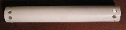
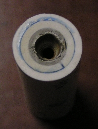
This is a
3/4" nominal PVC motor casing for four grains 1-3/8" long with the holes
drilled and before the header or nozzle has been cast. |
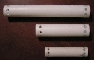
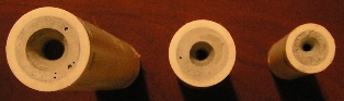
Here are three motor
casings with the nozzles cast and formed. They are a 1/2" 2 grain,
3/4" 2 grain and a 3/4" four grain. |
These are the same three
motors shown to the left and showing the nozzles cast in place with the
divergent cones. Notice the small bubbles in the first two.
These don't affect the strength. Also, the one on the left looks
larger but it is only because it is taller and so closer to the camera
lense. |
| |
|
|
 |
LEFT:
Here you can see the top header cast in place. All these are test
motors and none have delay charges so have solid headers (top closures). |
 |
|
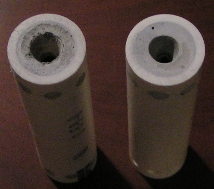
RIGHT:
The motor on the left has been successfully fired, the one on the right
has not been fired yet. You can see there is very little erosion
on the one that was fired. It had steel washers embedded in the
throat.
|
I.D. Retaining Ring
I first thought of this method after reading in John Wickman's book how to
use a split riing of of pvc pipe as a rocket pvc air frame coupler. I
thought if it works for an airframe, it ought to work for a motor nozzle
retainer... and it did... very nicely. Sam Grado then pointed out to
me that Chuck Knight had already published this exact method on Richard
Nakka's web site:
http://members.aol.com/ricbnakk/pvcmot1.html. So, thanks to John
for his method that made me think of this method, thanks to Sam for pointing
out that chuck had been doing this first, thanks to Chuck for his great web
page showing how to use this method and Chuck gets the recognition for the
method (until someone else claims to have been first) and Thanks to Richard
for providing the space on his web site. There is nothing new under
the sun and logic will usually drive towards the same few solutions to any
problem.
This retaining method is my favorite method because it is relatively easy
and it is as strong as using a cap or other fitting yet it gives a minimum
diameter motor and has a smooth outside with nothing on the surface, not
even the concrete holes which show up in the previous method even though
they are flush with the outside.
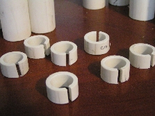
The I.D. retaining ring is made by cutting a piece off from the next smaller
size PVC pipe, i.e. cut a piece of 1/2" pipe for a 3/4" motor casing.
Regular pvc pipe cement is used to glue the ring into the end of the case.
I make my nozzles and headers the same length as the inside diameter of the
casing and the ID ring half the case ID in length. This ring then is
split because as is, it won't fit. Splitting it allows it to be
compressed and slid inside. There will be a small gap after installation but
this is no more a place for leakage than between the concrete and the case
wall. Actually, if a motor is going to leak exhaust gases, it is going
to leak there first because there is a smaller distance between the chamber
and it than the chamber and the outside. The same holds true for the
circumferential holes. To compensate for this, a seal of RTV silicone
rubber can be added as a fillet between the concrete and case. At
lower pressures, the RTV is not necessary.
Click on
pictures for larger image.
 |
 |
|
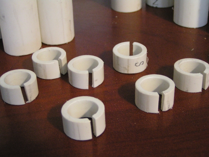
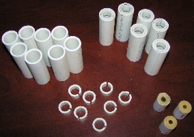
This is a
batch of 3/4" two grain motor casings, I.D. retainer rings, casings with
retainer rings installed and fuel grains ready to load. |
A closer
look at the retainer rings. I cut these using a 1/8" thick metal
cutting abrasive blade in my table saw and split them with the same
blade. The 1/8" split was the perfect width slot. |
| |
|
 |
 |
|
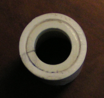
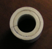
Retainer
ring installed into casing. Notice how small the gap is after the
ring is installed. |
Here is a
completed ID retainer ring motor that was successfully fired. The
blue is the pvc pipe cement. The picture on the left used a clear
pvc pipe cement. |
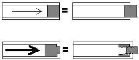
Squeezing
This method is
a bit of an oddity to me and I have never seen it used but I am adding it
here just to show that there are all kinds of ways to do anything and
retaining nozzles and headers is no different. I saw this used
someplace as a method to hold an ejection charge in a large diameter (4" or
more) high power rocket. I tried it on a piece of 1/2" pvc pipe
because I figured if it would work to reduce the diameter of something that
small and stiff, it would work for any larger size even better. The
concept is to wrap a heavy rubber band as tight as possible around the end
of a piece of pvc pipe where you want it squeezed. Then you put that
end into boiling water and as the pipe softens, the rubber band necks the
pipe down at that spot. The technique works fine but just make sure to
use new rubber bands. Old ones (if they are too old) will just snap,
spraying boiling water out of the pan. This method could be used for
the nozzle end but not for the upper closure because you couldn't put a
motor with a grain already installed into the water. It would be
ruined. At least sugar propellant would. Possibly epoxy
propellant or composite would work for both ends. It might look
interesting because it kind of looks like the shape of a nozzle, even though
the real nozzle is formed from concrete on the inside.
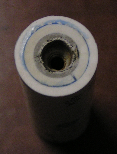
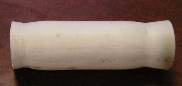 I tried both
ends on this one. The first one was higher up on the tube so I tried
it again lower down. It may not look like it squeezed that much but it
went from .606" dia. I.D. down to .482" dia I.D. after squeezing That
is a 33% reduction in cross-sectional area.. That is quite sufficient
to retain a concrete nozzle. I tried both
ends on this one. The first one was higher up on the tube so I tried
it again lower down. It may not look like it squeezed that much but it
went from .606" dia. I.D. down to .482" dia I.D. after squeezing That
is a 33% reduction in cross-sectional area.. That is quite sufficient
to retain a concrete nozzle.
Screws / Pins
This is a
common method to hold steel nozzles in a metal case. It could also
conceivably be used to hold a concrete nozzle or header in a pvc pipe motor
case. You would have to use quite a number of pins in order to have an
adequate shear strength. This method would have a similar effect as
the circumferential holes method but not even as good and it undoubtedly
would be a lot more work and expense.
Home ||
High Power Rocketry ||
Experimental Rocketry
|